|
Advanced Simulated Radar Client Copyright 2002
|
Configuration
This section describes how to setup ASRC, and how to configure user preferences.
Ports and Firewalls
ASRC uses the following ports:
6809 (TCP) for aircraft data
3782 (TCP and UDP) for air-to-ground communications
3290 (TCP and UDP) for ground-to-ground communications
·
If you
are using a firewall, you should open these ports when ASRC is running.
·
If you
are using a network address translation device (NAT) such as a router, or
Internet Connection Sharing (ICS), you should forward these ports to the
computer on which you are running ASRC.
·
If you
are experiencing difficulties with ASRC, and are using a firewall that does not
allow you to open individual ports, reduce the security level, or disable the
firewall during ASRC use.
Load sector file
To load a sector file:
1. On the FILE menu, click OPEN
2. Select the sector file that you wish to use
3. Click OK
Select Display Mode
ASRC has several different display modes:
DSR (Display System Replacement) is used by Centers.
ARTS-III mode is normally used by TRACONS.
Tower mode is similar to ARTS-III except that datatags are always turned on.
Ground mode shows limited datatags that are always turned on.
Another mode, to be released in version 2 of ASRC is the Eurocontrol style interface..
To select between the available modes:
1. On the OPTIONS menu, click RADAR TYPE
2. Move your mouse to the right, and click the desired mode.
Opening, closing, and repositioning windows
All windows in ASRC are transparent. Radar images and targets may be viewed through most items. Most windows in ASRC may be “rolled” open or closed. To open or close a window, click on its title bar. To reposition a window, drag the window to another location, and drop it there.
ATIS
To set your ATIS:
1. On the OPTIONS menu, click SETTINGS
2. Enter your ATIS information into the box labeled ATIS
3. Click OK to close the SETTINGS box
Aliases and alias functions may be used inside of the ATIS to create very useful information for pilots. See Alias section below for more detailed description of aliases.
For example, the following ATIS:
$radioname()
$metar($arr)
Will display an ATIS similar to the following:
Socal Approach
KLAX 181550Z 26006KT 8SM BKN018 BKN022 20/16 A3003 RMK AO2 SLP167 T02000156
In this example, the voice frequency, and radioname will automatically reflect your current information, even if you change servers, and the metar will be for the requestor’s destination airport. Theoretically, you will never need to update your ATIS again.
Select keys
ASRC uses two very important user configurable keys to perform functions on aircraft and on air traffic controllers. You will use these keys constantly, so chose keys with which you are comfortable.
The aircraft select key is used to select an aircraft for radio transmissions. The controller select key is used to select a controller for chat, or to handoff or pointout an aircraft to a controller.
The default aircraft select key is the numpad “+” key (called <asel> throughout the rest of this manual)
The default controller select key is the “\” key (called <csel> throughout the rest of this manual)
To select the Aircraft Select key:
1. On the OPTIONS menu, click SETTINGS
2. Enter the single character that you wish to use into the box labeled AIRCRAFT under SELECT KEY
To select the Controller Select key:
1. On the OPTIONS menu, click SETTINGS
2. Enter the single character that you wish to use into the box labeled CONROLLER under SELECT KEY
Visibility range
The visibility range within ASRC will be saved from session to session. For this reason, it is imperative for saving bandwidth on the network that you reduce your range to an acceptable level for each position. You will no longer need very wide visibility ranges in ASRC. Due to recent server modifications, you will see other control positions if your ranges touch. This is in contrast to previous server versions, where other controllers had to fall within your visibility range to be visible.
Visibility center
In extreme cases, where you wish to center way off to one end of your airspace, and you are concerned that your range may not overlap with another controller’s airspace, you may set a fixed visibility center. This will persist until you restart ASRC or until you load a new sector file.
To set a fixed visibility center, type:
.vis POINT <enter>
For example:
.vis GFS <enter>
.vis KLAX <enter>
or
.vis CIVET <enter>
To clear a fixed visibility center, type:
.vis <enter>
Alias File
To select the alias file:
1. On the OPTIONS menu, click SETTINGS
2. Click the BROWSE button next to the ALIAS FILE selection box
3. Select the alias file that you wish to use
4. Click OPEN
5. Click OK to close the Settings box
ASRC supports new robust alias features. An alias is simply a “macro”. In its simplest form, aliases enable the user to type a short text string, and have it replaced by a much longer string of text.
For example, if you set up an alias in your alias file that says:
.cdron cleared direct $1, resume own
navigation
… and on the text input line within ASRC you type:
.cdron RZS
… and the aircraft N12345 is currently radioselected, ASRC will send the following message to the pilot:
N12345, cleared direct RZS, resume own navigation
All previous alias files are supported, with one caveat. You will need to strip the $aircraft variable from the beginning of each line. ASRC automatically places the aircraft ID for the currently selected aircraft at the beginning of each alias-based radio transmission.
In ASRC, aliases are “concatenated”. This means that if you type one alias after the next on the input line, it will execute both aliases.
For example, if you set up an alias in your alias file that says:
.tr turn right heading $1
… and you have another one that says:
.cm climb and maintain $1
… and on the text input line within ASRC you type:
.rt 290 .cm FL280
… and the aircraft N12345 is currently radioselected, ASRC will send the following message to the pilot:
N12345, turn right heading 290 climb and maintain FL280
ASRC supports multiple “arguments” to the aliases. You may pass up to 9 arguments to the aliases.
For example, if you set up an alias in your alias file that says:
.trcmd turn right heading $1, climb and
maintain $2, cleared direct $3 when able.
… and on the text input line within ASRC you type:
.trcmd 270 13000 RZS
… and the aircraft N12345 is currently radioselected, ASRC will send the following message to the pilot:
N12345, turn right heading 270, climb and maintain 13000, cleared direct RZS when able
ASRC has many internal variables that make aliases extremely powerful.
$squawk (returns the squawk code assigned to the radioselected aircraft)
$arr (returns the arrival airport of the radioselected aircraft)
$dep (returns the departure airport of the radioselected aircraft)
$cruise (returns the assigned cruise altitude of the radioselected aircraft)
$temp (returns the assigned temporary altitude of the radioselected aircraft)
$alt (returns the assigned temporary altitude, if it exists, otherwise returns the assigned cruise altitude of the radioselected aircraft)
$calt (returns the current altitude of the radioselected aircraft)
$callsign (returns the controller’s callsign)
$com1 (returns the primary radio frequency of the controller)
$myrealname (returns the real name of the controller)
$winds (returns wind at the destination airport if airspeed >= 30 KTS, and departure airport if <30KTS)
$myrw No Longer Used.
$mypvtrw No Longer Used.
ASRC has many internal functions that make aliases even more powerful.
$metar(ICAO) (returns the metar at the ICAO airport in the parentheses)
$altim(ICAO) (returns the altimeter setting at the ICAO airport in parentheses)
$wind(ICAO) (returns the wind at the ICAO airport in parentheses)
$dist(POINT) (returns the distance to the POINT (airport, VOR, NDB, or FIX in parentheses)
$oclock(POINT) (returns the clock position of the POINT (airport, VOR, NDB or FIX in parentheses)
$bear(POINT) (returns the cardinal compass direction from the POINT (airport, VOR, NDB, or FIX in parentheses)
$radioname(CC) (returns the full spoken radio name of controller CC, yours if empty parentheses)
$freq(CC) (returns the radio frequency of controller CC, yours if empty parentheses)
Here is an example of the level of sophistication achievable with this enhanced alias language:
If you set up an alias in your alias file that says:
.rais the airport is at your $oclock($arr) and $dist($arr), report it in sight.
… and on the text input line within ASRC you type:
.rais
… and the aircraft N12345 is currently radioselected, ASRC will send the following message to the pilot:
N12345, KVCV is at your 11 o’clock and 9 miles, report it in sight.
Aliases may be used inside of the ATIS to create very useful information for pilots.
For example, the following ATIS:
$radioname()
$metar($arr)
Will display an ATIS similar to the following:
Socal Approach
KLAX 181550Z 26006KT 8SM BKN018 BKN022 20/16 A3003 RMK AO2 SLP167 T02000156
In this example, the voice frequency, and radioname will automatically reflect your current information, even if you change servers, and the metar will be for the destination airport of whichever pilot requests it. Theoretically, you will never need to update your atis again.
Position File
ASRC uses a position file (POF) to standardize features of the controlling experience. This file is used to create unique static controller position ID's for your ASRC radar client.
To load a Position File:
1. On the OPTIONS menu, click SETTINGS
2. Click the BROWSE button next to the POSITION FILE selection box
3. Select the alias file that you wish to use
4. Click OPEN
5. Click OK to close the Settings box
After importing a POF, the two-digit identifiers next to each controller in the controller list (CL) will be the same each time you use ASRC. Consequently, you can memorize two digit controller ID’s to be used for handoffs, pointouts, and text communications. Without a POF, ASRC will still function normally; however, controller ID’s will be assigned by ASRC and are likely to be different each time you use the program requiring you to look at the CL each time you wish to perform a function requiring the ID. Additionally, ground-to-ground VSCS buttons are created based upon information in the POF. For this reason, you must create a POF prior to creating VSCS buttons for ground-to-ground voice communications.
You may use the ZLA.POF as a template for creation of your own POF. Use a standard text editor, and save the file with the extension “.pof” Be sure to follow the files structure exactly. Do not allow any controllers in the POF to have duplicate controller ID’s, or only the first entry will be valid.
Amending the POF file only changes the way controllers appear to you, and does not affect the way other clients see you, or the way that they see other controllers.
The position file uses the following format:
NAME:RNAME:FREQ:SECID:ARTSTAG:CALLPREFIX:CALLSUFFIX:LINE1:LINE2
where:
· NAME = The name you wish to see in drop down lists.
· RNAME = The name you wish to be displayed on the radio for this position.
· FREQ = The unique valid frequency for this position.
· SECID = The two digit sector ID that you wish to use for identifying this controller for handoffs, pointouts, comms, etc.
· ARTSTAG = The single letter or number that you wish to use as an aircraft position indicator for aircraft owned by this controller when in ARTS-III mode.
· CALLPREFIX = The callsign prefix that this controller must be using.
· CALLSUFFIX = The callsign suffix that this controller must be using.
· LINE1 = The first line to display on VSCS ground-to-ground buttons created for this controller.
· LINE2 = The second line to display on VSCS ground-to-ground buttons created for this controller.
·
LSQUAWK = LOW END OF
·
HSQUAWK = HIGH END OF
A “-“ in place of RNAME indicates that it is the same as in the previous field.
A “-“ in place of the SECID indicates that you wish to recognize this position as an observer, rather than a valid control position.
For example:
Los Angeles Center:-:125.800:20:C:LAX:CTR:LAX:CTR:7301:7477
Indicates that:
1. The
sector name is
2. The
radio name is
3. The valid frequency is 125.800
4. The assigned Sector ID is 20
5. The ARTS tag position indicator will be the letter “C”
6. The callsign prefix must be LAX
7. The callsign suffix must be CTR
8. The VSCS button will display LAX on the first line
9. The VSCS button will display CTR on the second line
10. The lowest squawk code available for assignment by this position is 7301
11. The highest squawk code available for assignment by this position is 7477
When a controller logs on, he will only be tagged with the appropriate controller ID from the POF if the following three items match the POF entry:
1. Callsign prefix (eg. LAX for LAX_V_CTR)
2. Callsign suffix (eg. CTR for LAX_V_CTR)
3. Frequency (eg. 125.8 for LAX_V_CTR)
Note that as long as the controller is on 125.8, the following will all match:
1. LAX_V_CTR
2. LAX_I_CTR
3. LAX_CTR
4. LAX_DH_CTR
5. LAX_C_CTR
It is critical to assign the correct prefix, suffix, and frequency to each entry in the POF. Additionally, it is important for controllers to remember that if they select a non-standard frequency, other controllers may not have the same controller ID and VSCS buttons set up for the controller.
If no squawk range appears on a given line, squawk codes will be assigned from the range entered into the settings window.
Squawk Range
Using ASRC, the controller assigns unique squawk codes to each aircraft under his control. ASRC uses a range of squawk codes from a pool defined by the user. When an aircraft is radioselected, pressing F9 and then <asel> once again will assign a unique squawk code to that aircraft. It does this by first polling all aircraft in radio range, all controllers in visibility range, then assigning the next available squawk code from the user-defined range that is not currently in use or reserved by a controller.
To select the range of available squawk codes:
1. On the OPTIONS menu, click SETTINGS
2. Enter the lower end of the squawk range in the left box, and the upper end in the right box
3. Click OK to close the Settings box
VFR Squawk Code
Set the single code used by VFR aircraft in your area of operation (default 1200).
Transition Altitude
Set the transition altitude for your area of operation (default 18000).
Conflict Alerts
In DSR mode, separation conflicts cause the entire datatag to flash. In ARTS mode, the two letters CA appear above each datatag to indicate aircraft in conflict. ASRC enables users to select a distance and altitude separation for each of the two modes (DSR or ASRC). Additionally, you may set a floor, below which you will not see conflict alerts.
To select the conflict parameters:
1. On the OPTIONS menu, click SETTINGS
2. Enter the distance and altitude separation that will trigger an alert for each mode
3. Click OK to close the Settings box
Voice enhancements
One of the most exciting new features of ASRC is the integration of voice into the controller interface. ASRC channels sound as it wishes, and enables us to use voice for a rich array of functions. Using an interface called the VSCS (Voice Switching & Control System), ASRC now allows us to have the same voice functions as are used in ATC facilities around the world, including:
1. Override
2. Intercom
3. Monitor
4. Group call
To select the push-to-talk key for the use of voice through ASRC, type:
.ptt <enter> <push-to-talk key that you wish to use>
We suggest using the right CTRL key to avoid conflicts with other important ASRC keys.
IMPORTANT: You must select the push-to-talk key at least
once or you will not be able to use voice through ASRC!
Event sounds
To setup event sounds:
1. On the OPTIONS menu, click SOUNDS
2. On the dropdown menu, select the event for which you would like to assign a sound
3. Click the BROWSE button, and select the sound that you would like to attribute to this event
4. Click OPEN
5. If you wish to test the sound, click PLAY
6. Click OK to close the SOUNDS box
The DC (Display Configuration)
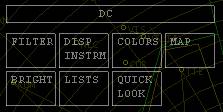
The DC is the panel of soft configuration buttons, which by default, resides in the upper left corner of the display. Click on the DC bar to open or close the first level of buttons.
The DC is where most of the day-to-day changes in configuration are made. There are three classes of buttons. One class increments or decrements a value. To increase the value in this button, click in the upper portion of the button. To decrease the value in the button, click in the lower portion of the button. The second class of buttons toggle a function on or off with a single click. The third class of buttons open a sub-menu.
Filters
ASRC enables controllers to turn off certain aircraft within certain altitude strata.
USE CAUTION with the following command. Under most circumstances it should NOT BE USED. To set HARD FLOORS AND CEILINGS to your airspace strata, through which NOTHING WILL BE VISIBLE UNDER ANY CIRCUMSTANCES type:
<F2> FFFbCCC <enter> (where FFF is a three digit floor in hundreds of feet, and CCC is a three digit ceiling in hundreds of feet)
To reset the hard floor and ceiling, type:
<F2> 000b999 <enter>
The preferred method for turning on and off altitude strata is through buttons on the DC (Display Configuration). Make sure that the DC is unrolled, revealing the first group of buttons.
The advantages of using the DC to limit altitude strata are that:
1. Handoffs will override any filter settings
2. Pointouts will override any filter settings
3. Filter settings can be set to allow aircraft in arrival and departure lists to override any filter settings.
Click the FILTERS button to open and close the group of buttons pertaining to FILTERS.
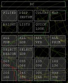
The buttons within the FILTERS section determine which aircraft will be displayed. By default all buttons are on, indicating that all aircraft will be displayed at all altitudes.
The following section describes the function of each filter button, which toggles the display of:
1. ALL FDB – full datablocks at all altitudes (this should always be left on)
2. ALL LDB – limited datablocks at all altitudes.
3. ALL VFR – aircraft squawking 1200 at all altitudes.
4. ALL PRIM – all primary targets (this should always be left on)
5. Select Beacon – the beacon slash only for aircraft in arrival and departure lists
6. Select LDB – the beacon slash and limited datablock for aircraft in arrival and departure lists
7. Altitude strata – aircraft in each altitude strata
To turn a button on or off, simply click within the box.
Display Instruments
The Display Instruments section sets values for various items on the display.
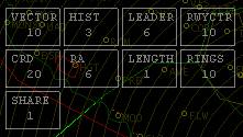
VECTOR sets the length in nautical miles of the vector line (distance line)
HIST sets the number of history trails to be displayed
LEADER sets the default leader line direction
RWYCTR sets the runway centerline length in nautical miles
CRD sets the number of lines to display in the upper panel of the CRD display
RA sets the number of lines to display in the RA portion of the CRD display
LENGTH sets the default leader line length
RINGS sets the distance between range rings
SHARE sets the toggling speed between altitude/groundspeed and scratchpad values in ARTS mode
Colors
The COLORS button opens a panel of buttons to set colors within ASRC. Each button on the sub-panel opens a dialog box enabling customization of ASRC colors.
Map Features
The MAP button opens a panel of buttons allowing the controller to toggle on and off various sector file features including airports, VORs, fixes, airways, geographical features, etc.
Brightness
The BRIGHTNESS button opens a panel of buttons allowing the individual setting of brightness for various different ASRC features.
Lists
The LIST button toggles a sub-menu with three additional buttons, the RQST, ARR/DEP, and HOLD buttons.
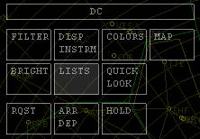
When REQUEST, ARRIVAL, DEPARTURE, or HOLD list items are generated (see Usage), the respective button turns gray. Pressing the button toggles the display of the desired list on and off to free up additional screen real estate. If new items are added to a list, the list will automatically re-appear.
Arrival Lists
Arrival lists show aircraft inbound to any number of user-specified airports. This list is displayed automatically whenever entries are added or auto-generated based upon user settings. If arrival entries exist, the arrival list may be toggled off and on using the LIST buttons described above.
The format for the arrival list is:
LETTER AIRCRAFT A APT DIST
LETTER is the single alphabetical letter representing that aircraft in the list. This is used to quickly pull up information about that aircraft.
AIRCRAFT is the full aircraft callsign
A is the single letter A to let us know that this is an ARRIVAL
APT is the ICAO ARRIVAL airport ID
DIST is the distance in miles from the arrival airport
For example:
A N12345 A KLAX 153
B SWA998 A KLAX 50
To add or remove airports that you will be monitoring:
1. On the OPTIONS menu, click SETTINGS
2. Enter the four letter airport designator that you wish to monitor in the box above DEPARTURES/ARRIVALS
3. Click ADD or REMOVE
4. Click OK to close the Settings box
Aircraft may also be manually added to, or removed from your arrival list. See usage section.
Departure Lists
The DEPARTURE LIST shows aircraft outbound from any number of user-specified airports. This list is displayed automatically whenever entries are added or auto-generated based upon user settings. If departure list entries exist, the departure list may be toggled off and on using the LIST buttons described above.
The format for the departure list is:
LETTER AIRCRAFT D APT SQUAWK
LETTER is the single alphabetical letter representing that aircraft in the list. This is used to quickly pull up information about that aircraft.
AIRCRAFT is the full aircraft callsign
D is the single letter D to let us know that this is a DEPARTURE
APT is the ICAO DEPARTURE airport ID
SQUAWK is the squawk code
For example:
A N12345 D KLAX 7201
B SWA998 D KLAX 7202
To add or remove airports that you will be monitoring:
7. On the OPTIONS menu, click SETTINGS
8. Enter the four letter airport designator that you wish to monitor in the box above DEPARTURES/ARRIVALS
9. Click ADD or REMOVE
10. Click OK to close the Settings box
Aircraft may also be manually added to, or removed from your arrival list. See usage section.
Aircraft may also be pushed to another controller’s departure list. See usage section.
Range rings
To use range rings:
1. Set a visible color for the range rings (see colors menu).
2. Turn on range rings in the MAP menu of the DC.
3. Center range rings on a specific location (fix, VOR, or airport) by typing:
.rings POINT <enter>
where POINT is any fix, VOR, or airport
VSCS (Voice Switching & Control System)
The VSCS is the communications center of ASRC. When a frequency is changed in ASRC the voice and text frequency are simultaneously changed.
Prior to loading ASRC, and prior to using voice features for the first time, open Roger Wilco, set it to use voice activation, and set it to maximum sensitivity. Then change the mute key to the left control key. Close Roger Wilco prior to launching ASRC. ASRC will launch Roger Wilco automatically once voice enhancements are enabled.
In ASRC the right control key will be your push to talk key.
To toggle the VSCS open or closed press the TAB key.
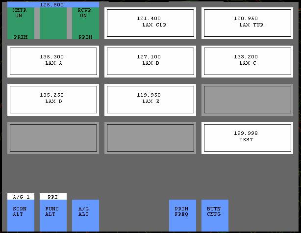
To configure the Air-to-Ground buttons:
1. If the VSCS is closed, press TAB to open the VSCS
2. If the first button on the lower left does not say A/G 1 at the top, click on the SCRN ALT button, then A/G 1
3. Click BUTN CNFG, it will begin flashing
4.
Click one of the rectangles in the upper portion of
the VSCS
5. Enter the frequency that you want the button to represent
6. Enter a station ID that will help you recognize the button
7. Enter the Roger Wilco room frequency as the pilot should type it in (excluding the server)
8. Click OK
You may configure as many buttons as you wish. They will be saved when you exit ASRC.
To set your primary frequency:
1. If the VSCS is closed, press TAB to open the VSCS
2. If the first button on the lower left does not say A/G 1 at the top, click on the SCRN ALT button, then A/G 1
3. Click PRIM FREQ, it will begin flashing
4. Click on any already-configured frequency button.
5. It will open and change color.
There are three positions on each
pre-configured Air-to-Ground button. The
first position is the transmit position (
Secondary frequencies may be turned on in either transmit only, receive only, or both. If either transmit or receive are turned off, but the other is on, it applies equally to both voice and text.
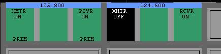
In the above example, the controller is able to transmit and receive on 125.800 (text and voice), but on 124.500, he is receiving only (text and voice).
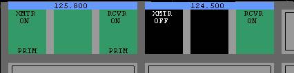
In the above example, the controller is again able to transmit and receive on 125.800 (text and voice), but on 124.500, he is receiving only (this time text only).
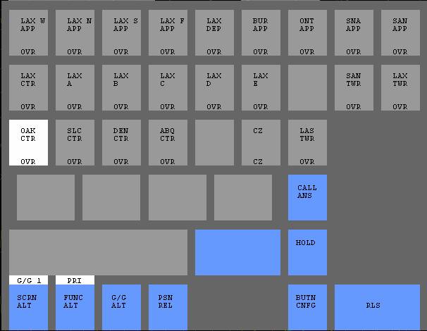
To set Ground-to-Ground buttons (for controller-to-controller voice communications:
1. If the VSCS is closed, press TAB to open the VSCS
2. If the first button on the lower left does not say G/G 1 at the top, click on the SCRN ALT button, then G/G 1
3. Click BUTN CNFG, it will begin flashing
4. Click
one of the small rectangles in the upper portion of the VSCS
5. Click one of the four button types listed
6. Select the position from the drop down list
7. Click OK